Seat belt upper mount


We’ve sold rear seatbelts for the T3 for a good many years now, initially designed for retro fitting into the rear of a Westfalia T3 models but soon people were asking if we could adapt the kit to suit panel van conversions, naturally we obliged.
The way we got around the lack of factory mounting points was to use universal strengthening plates, it was a solution that worked but could have always been better.
We recently broke a knackered old T3 Caravelle and as some of you know that they had factory seat belt mountings (Models 251 and 252 don’t have factory seatbelt mountings, basically Panel vans where models 253 to 256 Kombi/Caravelle have factory seat belt mountings) so we chopped out the panels and the strengthening, drew them up and sent them off to the machine shop for fabricating.
Naturally with most UK converted “campervans” starting life as basic panel vans they don’t have the factory fitted seatbelt mountings these brackets should help a nice tidy seatbelt install for some customers.
The factory design as been ever so slightly adapted to allow retro fitment without welding and retains the strength that VW built in.

For some reason we’ve sold loads of seatbelts recently but we haven’t been asked to fit any so when we had the opportunity to fit one for a customer the other day it seemed like a perfect opportunity to take a few pictures.

Van was a late Auto-sleeper, obviously we needed to strip out the rear panelling first.

Tools required.

  • Scissors [to cut out the drilling template]
  • Centre punch.
  • Drill
  • 5mm drill bit
  • 17mm drill/hole saw/cone cut.
  • Rivet gun.
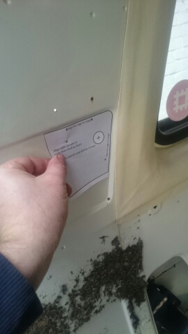
T3 Seatbelt template
First start by cutting the template out, there are 2 supplied, one for the left, one for the right. Align the circles on the template with the dimpled in the bodywork.
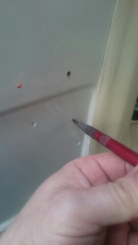
T3 seatbelt centrepunch.
Centrepunch through the template to mark where to drill the hole for the seatbelt mounting. Yes, we know, there is no template in the picture! I centre punched it lightly and this was me going over the mark.
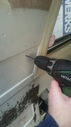
Drill
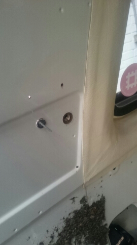
Using the 5mm drill, drill out the rearmost dimple, this hole will be used to rivet the plate into place.
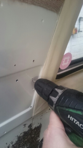
Drill drill drill.
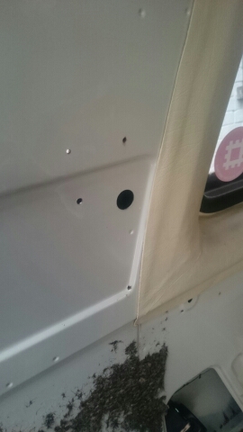
….and then drill the centre popped mark.
Punch!
Instead of drilling this hole we used a sheet metal punch that bolts together, the bolt in the middle is tightened and it punches a nice clean hole out. You could use a drill bit, a hole saw or a cone cutter/step drill to do this but please be careful not to mark the panel behind!
Prime and paint.
Once the hole is punched through then prime and paint any bare metal edges.
image
Once the paint is dry it’s time to slide the mounting plate into place. You’ll have to take the rear pillar vent out to do this. Align the plate using the rivet and dimple in the metalwork.
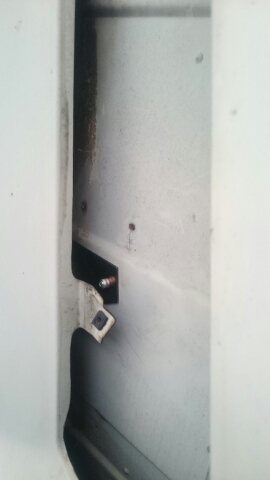
image
View of the riveted plate in situ with the plastic vent removed.
image
View of seatbelt loosly fitted inside the panel.
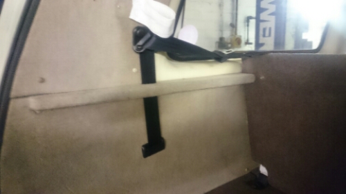
image
All back together, trim panel fitted and the parcel shelf bracket trimmed for free movement of the belt.

Seatbelt mounting bracket
Seatbelt kit – Rear Left
Seatbelt kit – Rear Right
Seatbelt trim – T3 / T4
Seatbelt mounting bracket – Bulkhead
Outer mounting brackets – Left and Right

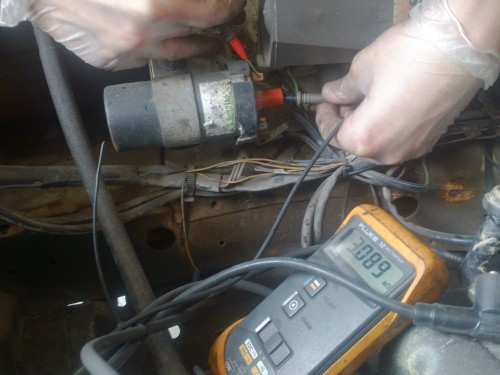
 

T3 Ignition checks – Ignition coils

On a VW T3, from the factory there were 4 different ignitions coils fitted throughout the production run, one of them was only used in some African countries on models fitted with points style ignition and are unlikely to see them here so they will be glossed over.

Early vans were air cooled, the 1.6l “CT” engine and the 2.0l “CU” engine, they used what we call the early coil, it had DIN connection for the king lead, when the WBX joined the ranks then they too used the early coil. In July 1984 they swapped from the early DIN coil to the later “sawtooth” style connection at Chassis number WV2 ZZZ 25 Z EH 155 001

The later coils as fitted to everything else, these could either have a green coloured label on them or a grey label. ETKA [VW’s Electronic Parts Catalogue] is a little confusing regarding what vehicles have the green and which have the grey label, in fact the information is contradictory.
It turns out that vehicles with a grey label on their ignition coil were for vehicles with extended service intervals, basically they could go longer between having a service and as such had different 3 earth electrode spark plugs.
We feel the best way to get the right coil is just to fit what was on there originally.

A faulty ignition coil could cause a few different problems, we find that they start to give flat spots while driving, this is usually a sign they are past their best. They can be checked with a multimeter set to ohms (more on that later).

An ignition coil is basically a step up transformer encased in steel (or laterly aluminium) and filled with oil, there are 2 circuits, a primary and a secondary, the primary is the low voltage side, the secondary is where the high voltage is induced. 12v is supplied to the primary circuit and around 35000v is induced in the secondary coil which is then fed via the king lead to the distributor cap where it is dished up to the correct cylinder.

The primary circuit, this is the low voltage side, the outer terminals on the body. One is marked “15”, this is ignition live [Black wire]. The other terminal is marked “1”, this is what’s called the tachometric signal, this is the switched earth supplied by your ignition module to turn the coil on and off [Green wire].

The secondary circuit is between terminals 1 and 4, the green wire terminal and the HT output to the distributor cap.

Obviously you disconnect the electrical connections from the coil before you get busy with your Ohmmeter as you want to measure the resistance of the coil and not the rest of the ignition system too!

The expected resistances are listed in the table below.

  VW No Bosch No Fitted to Primary Secondary    
Early 211 905 115 B 0 221 122 023 CT, CU, DF, DG .52Ω to .76Ω 2.4kΩ to 3.5kΩ Up to 24 E 155 000
Late – Green label 211 905 115 D 0 221 122 349 DF,DG,DH,GW,DJ,MV,SS,SR .5Ω to .8Ω 2.4kΩ to 3.5kΩ From 24 E 155 001
Late – Grey label 191 905 115 A/B/C 0 221 122 399 DF,DG,SP,DJ .6Ω to .8Ω 6.9kΩ to 8.5kΩ    
DSC_0066
Testing the secondary resistance with an Ohmmeter

After testing, if you find the Ohms readings are out of specification then it’s time to change the coil, it’s as simple as that!